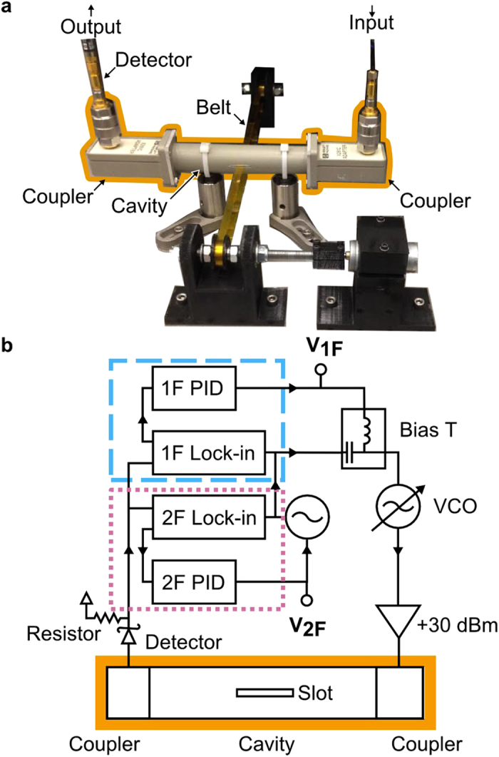
Figure 1. A diagram of the microwave circuit and corresponding photograph of the noncontact conductivity and dielectric constant measurement technique for high-throughput web processing.

(a) A photograph of the setup. (b) The setup uses a voltage-controlled oscillator (VCO) with a frequency (1F feedback loop, blue dashed line) and amplitude (2F feedback loop, pink dotted line) tracking. The cavity is outlined in orange.
