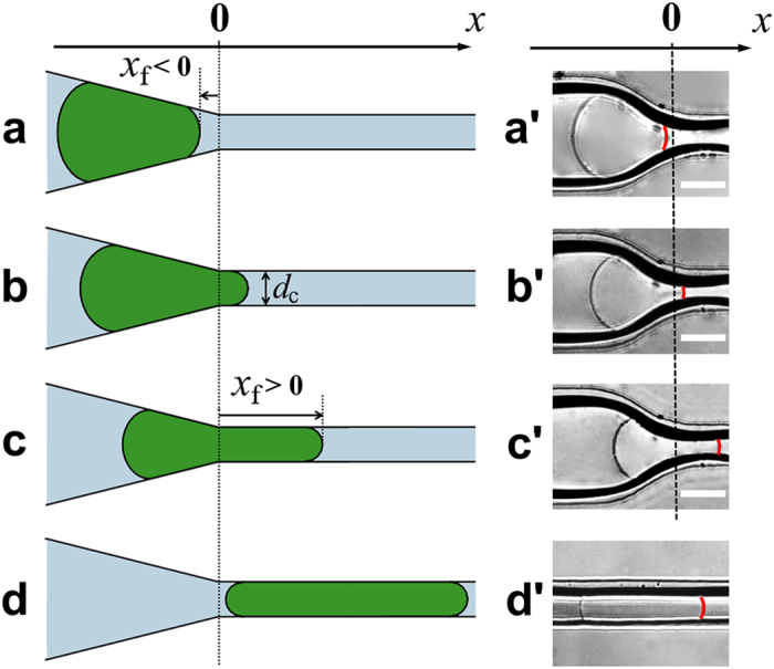
Figure 2. Microgel in different confined states.

(a–d) Schematics of the microgel in different positions along the microchannel. (a) Microgel is localized completely in the tapered zone with the axial position of its front tip, xf < 0. (b) A small portion of the microgel is located in the constriction of diameter dc, with a front tip position, xf > 0. The pressure difference across the microgel is dominated by its tapered portion. (c) A large portion of the microgel enters the constriction, with the length xf of the constricted microgel portion. The pressure difference across the microgel is dominated by its constricted portion. For xf > 0 in (b) and (c), the smallest diameter of the microgel in contact with the microchannel walls is dc. (d) The microgel is localized completely in the constriction. (a′–d′) Representative optical microscopy images of the microgel in the confined states corresponding to (a–d). The red line shows the front tip of the microgel. α = 30°. The scale bar is 100 μm.
