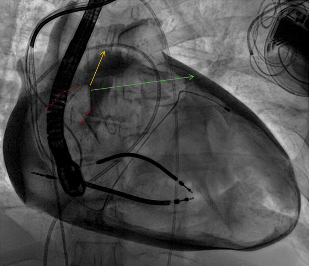
FIGURE 5. Exit Angle and Success.
In this contrast pericardiogram from another patient, the right atrial appendage border (dotted red line) is depicted along with 2 theoretical wire exit trajectories. Trajectory 1 (yellow) is aligned with the main axis of the right atrial appendage and oriented superiorly; failed right atrial exit along this trajectory may be related to the superior pericardial reflection. By contrast, trajectory 2 (green) is oriented more horizontally and leftward.

