
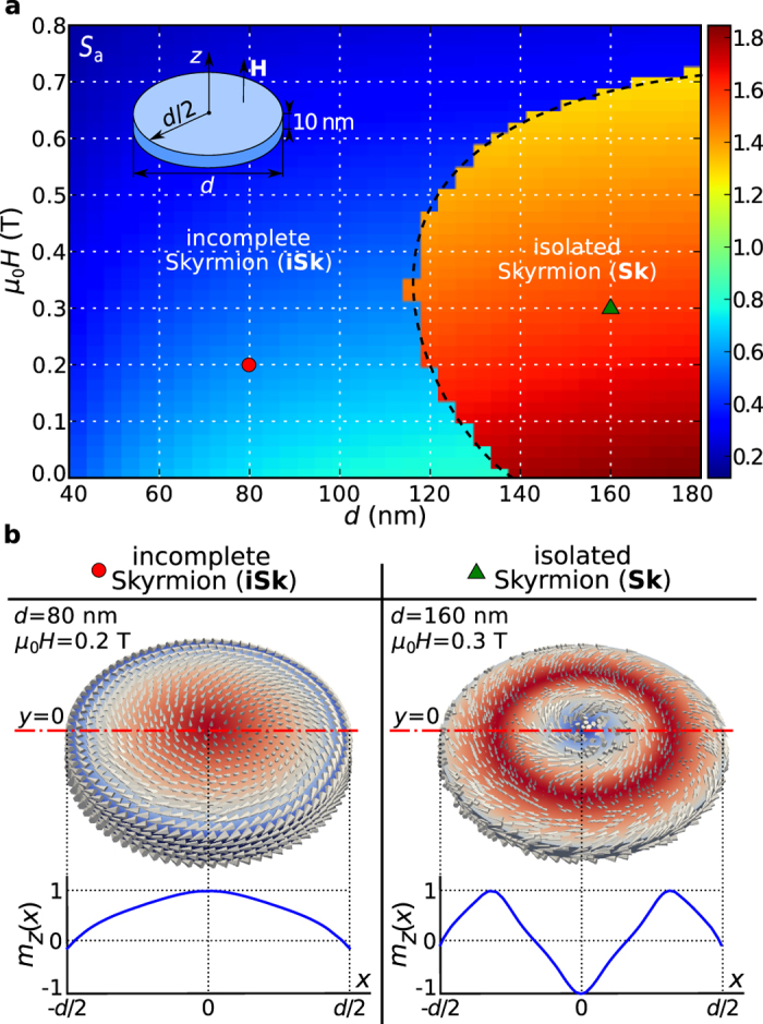
Figure 2. Thin film disk ground state phase diagram and corresponding magnetisation states.
(a) The scalar value  for the thin film disk sample with thickness
  as a function of disk diameter
  and external out-of-plane magnetic field
  (as shown in an inset). (b) Two identified ground states: incomplete Skyrmion (iSk) and isolated Skyrmion (Sk) magnetisation configurations at single phase diagram points together with their out-of-plane magnetisation component
  profiles along the horizontal symmetry line.