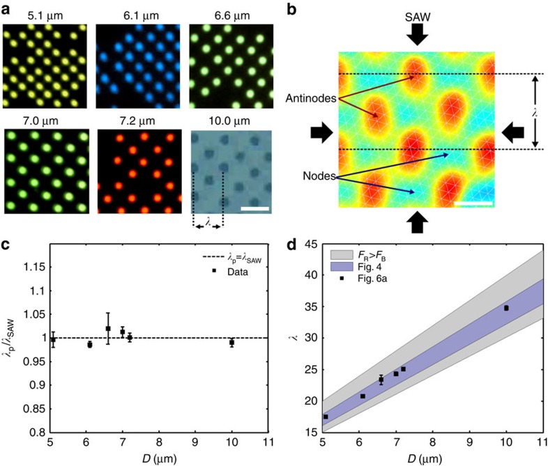
Figure 6. Characterization of the OCPW-patterning phenomena.
(a) Spherical particles of essentially any size can be patterned in the two-dimensional acoustic grid, here showing the patterning of 5.1-, 6.1-, 7.0-, 7.2- and 10-μm polystyrene particles in acoustic fields of different wavelengths actuated by a 204-, 171-, 149-, 145- and 101-MHz (respectively) signal at 0.38 W. Scale bar, 30 μm. (b) The position of these particles is dictated by the nodal positions in the acoustic field, with particles migrating to the minimum displacement locations in the field. The image shown here is a map of the maximum surface displacement on a λ=30-μm device as measured by a laser doppler vibrometer. Scale bar, 15 μm. (c) As expected, the distance between the patterned particles in a is proportional to the wavelength of the acoustic field, with λp/λSAW=1, where λp is 2 × the distance between particles in the x- or y-directions. (d) The OCPW-trapping region (as measured by λ/D) scales linearly with particle diameter, although the range of these values is somewhat smaller than predicted by equations 1 and 2 (see Supplementary Fig. 1), suggesting that these equations may lose some predictive power as the particle dimensions approach that of the acoustic wavelength. Error bars in c and d denote one s.d. of the measured particle spacings in a. Adapted from ref. 70.

