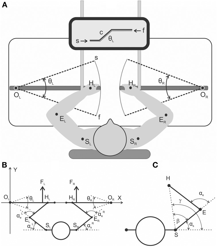
Figure 1.
(A) general scheme of the experimental setup from a top view (A) and a detailed geometry description regarding the relative arrangement of the moving arm segments and levers (B,C). (A) The subjects produced symmetrical bimanual movements using a visual tracking procedure. The target movements were executed via the combination of two beams on the monitor screen: the command signal (c) evolving with time as a trapezoid and the signal from the joint angle sensor of the left lever (θL). (B) General scheme of the experimental setup from a top view with a detailed geometry description regarding the relative arrangement of the moving arm segments and levers. Real parameters of the arm's segments (EH, ES) and the distance between the rotation centers at the shoulders (SLSR) were defined for each subject prior to the experiment. (C) Geometrical drawing used to define the precise joint angle changes in the shoulder and elbow joints (αs, αe) based on real records of the levers' turning angles (θL, θR); a detailed description is provided in the text.

