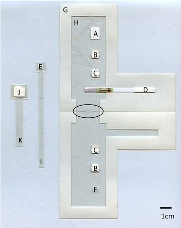
Fig. 1.

Layout and components of the paper and plastic amplification and detection device. The device is shown in its configuration just before it would be loaded with wet reagents. The sample sliders are shown off to the side for clarity. The slots where they would be inserted, which are cut into the hinge where the device folds shut, are highlighted with an oval outline. The components of the device are A the RPA pad; B the dry dilution pads; C the wet dilution pads; D the lateral flow strip; E the sample pad; F the mixing pad; G the base layer; H the acetate mask; I the sample slider; J the running buffer pad; and K the running buffer slider
