
Figure 1. Overall structure of MCU NTD .
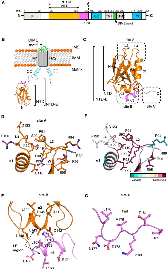
- Topology diagram of MCU in the IMM. Crystal structure of MCU NTD (orange) and MCU NTD‐E (20‐a.a. extension in magenta) is shown.
- Overall structure of MCU NTD and MCU NTD‐E. MCU NTD is composed of two helices (α1 and α2), six β‐strands (β1–β6), and two conserved loops (L2 and L4). MCU NTD‐E has an additional α‐helix (α3) and C‐terminal tail (magenta).
- Top view of L2 and L4 loops (site A in C), showing the hydrogen bonding and hydrophobic interaction. Residues are shown in stick, one water molecule (W1) as red dots. Dashed lines (red) denote hydrogen bonds. The putative phosphorylation site, S92, is described in stick in the L2 loop.
- Highly conserved L2 and L4 loops in MCU NTD by ConSurf analysis 61. Residues represented in the L2 and L4 loops are coloured according to conservation analysis by ConSurf, using 250 MCU NTD homologues selected from the UniRef90 database.
- C‐terminal hydrophobic helical regions (α2 and α3; site B in C). α2‐ and α3‐helices of the leucine‐rich (LR) region are shown in orange and magenta, respectively.
- Tail region (site C in C), showing the ubiquitination or biotinylation site K180 within MCU NTD‐E.