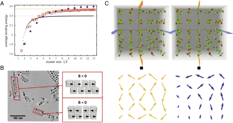
Fig. 4.
Assembly of cubic magnetic nanoparticles with corresponding mean dipole orientations. (A) Averaged magnetic binding energy per particle as a function of the cluster size. Black dots: linear chains of particles. Red squares: planar square clusters. Blue circles: cuboids. Gray line: asymptotic limit for linear chains of dipoles with head-to-tail magnetization. Orange line: asymptotic limit for square clusters of dipoles with in-plane antiferromagnetic order. (B) Cryo-TEM image of 1D and 2D structures of cubic nanoparticles, and a sketch of the corresponding dipole orientations. (C) Stereoscopic image of the calculated arrangement of minimal energy of 5 × 5 × 5 magnetic dipoles arranged in a cubic lattice. The black squares are a guide for the eyes to help find the right observation distance to obtain the stereoscopic impression. The yellow and blue arrows indicate the orientation of the dipoles within the planes indicated in the upper part.

