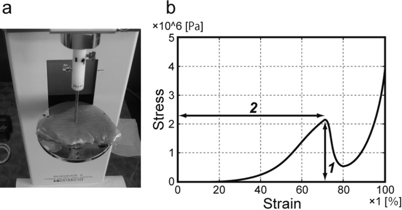
Fig. 2.

Photograph of the creep meter (a) and a typical stress–strain curve obtained by the creep meter (b). In (a), the ITL muscle is mounted on a plate and loaded compression stress using a plunger. In (b), ‘1’ indicates the failure stress, and ‘2’ indicates the strain at failure.
