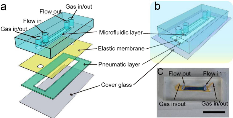
Figure 1. Schematic illustration of the vascular model chip.
(a) Details of the components of the chip. (b) The structure of the integrated chip. (c) A photograph of an actual chip. The dark blue part delineates the microfluidic channel and the orange part indicates the stretch chamber. Scale bar: 1.5 cm.

