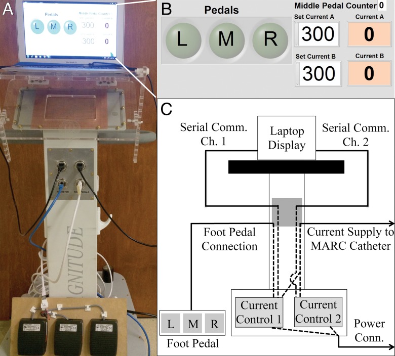
Figure 3:
A, Photograph of the catheter control system, with a laptop running the graphical user interface shown at the top and the foot pedal actuator shown at the bottom. B, Screen shot of the graphical user interface used to control current delivery to the catheter. On the left are indicators that are illuminated when the corresponding foot pedal is pressed. On the right are numerical fields where the user can enter the desired current value for each channel. C, Schematic depiction of the electrical connections between components inside and outside of the control system cart. The two printed circuit boards that are responsible for delivering electrical current to the MARC catheter are located at the bottom of the system. Dotted lines demonstrate connections made inside the cart, while solid lines demonstrate connections made outside the cart.

