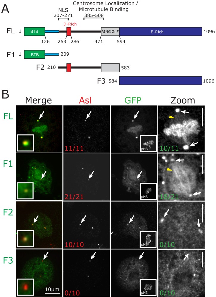
Fig 1. CP190 localization to the mitotic spindle is driven by its N-terminal region.
A, Domain structure of CP190. Shown is the BTB domain (green), linker (blue), D-rich domain (red), Zinc finger domain (grey), and the E-rich domain (blue). Indicated above the graphic representation are the previously identified nuclear localization signal (NLS) and the centrosome localization/MT binding domain [11]. Below the full length (FL) CP190 is a schematic of fragments used for this study (F1, F2, and F3). B, Drosophila S2 cells transfected with the indicated GFP-CP190 constructs (green). Shown are mitotic cells fixed and stained for Asterless (Asl, red) to mark centrosomes and pH3 (mitotic specific histone marker, inset in the GFP column). White arrows designate the centrosome. Red numbers on Asl column indicate the fraction of mitotic cells that exhibit GFP localization to centrosomes. Zoom of GFP channel (right column) is contrast enhanced to emphasize GFP signal on the mitotic spindle (yellow arrowheads). Green numbers indicate the fraction of mitotic cells with GFP signal at the spindle. Scale bars (B) = 10 μm, (zoom) = 5 μm.

