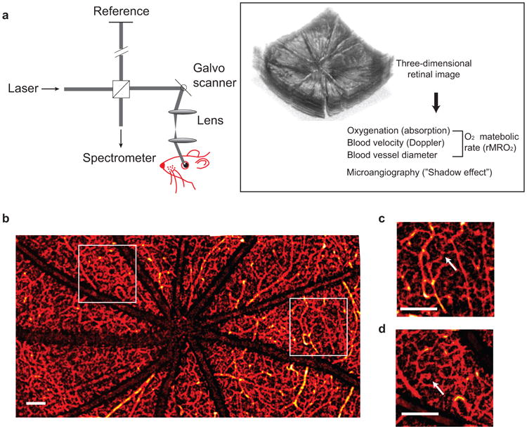
Figure 1.

Principle of vis-OCT retinal imaging. (a) Illustration of vis-OCT system. A laser beam with a bandwidth from 520 nm to 630 nm was focused onto the retina. The reflected light interferes with the reference light, and the interference spectral fringes were collected by a home-built spectrometer. The interference spectral fringes were used to reconstruct the echo reflected from different depths of the retina. As the focal point was scanned across the retina by galvo mirrors, the 3D retinal structure was obtained. Further post-processing calculated the rMRO2 and produced the retinal microangiogram. (b) Example of a wide-field view of retinal microvasculature imaged by vis-OCT. (c–d) Magnified view of the highlight squared areas in the panel b. The arrows highlight the smallest capillary vessels. Bar: 200 μm.
