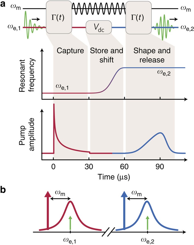
Figure 2. Protocol for mode conversion.
(a) A signal in the transmission line at frequency ωe,1 (green sinusoid) is first converted into a vibration of the aluminium drumhead (black sinusoid). Γ(t) is adjusted by varying the power in a pump at frequency ωe,1−ωm (red waveform). Then we alter the frequency of the microwave circuit by changing Vdc. During this time, the signal is stored in the vibrating drumhead; the change in Vdc adiabatically changes ωm by approximately 2π × 300 kHz. Finally, the signal is transferred from the drumhead back into the transmission line at frequency ωe,2 by adjusting the power in a pump at frequency ωe,2−ωm (blue waveform). (b) Frequency domain schematic of mode conversion. Microwave pumps (red and blue arrows) applied at a frequency ωm below the microwave circuit (response shown as the red and blue curves) allow a signal at frequency ωe,1 to be converted to a signal at frequency ωe,2 (green arrows).

