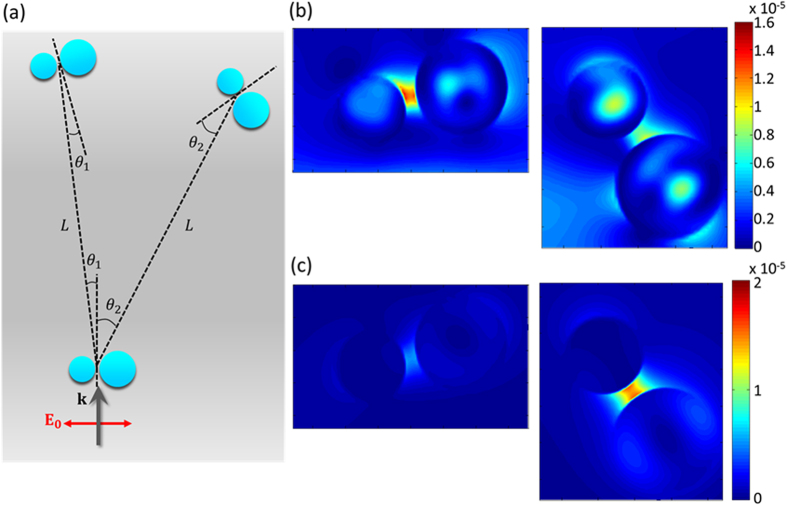
Figure 7.
(a) Schematic illustration of the configuration used for the demonstration of tuneable optical guide. The first dimer was illuminated by the incident light parallel to the substrate with polarization along the dimer axis. The second dimer was placed at either left (θ1 = 7.2°) or right (θ2 = 27°) from the first one. The separation distance is L = 1.2 μm. (b,c) The electric field intensity monitored at the second dimer with the wavelength of excitation at λ ~ 440 nm (b) and λ ~ 600 nm (c).

