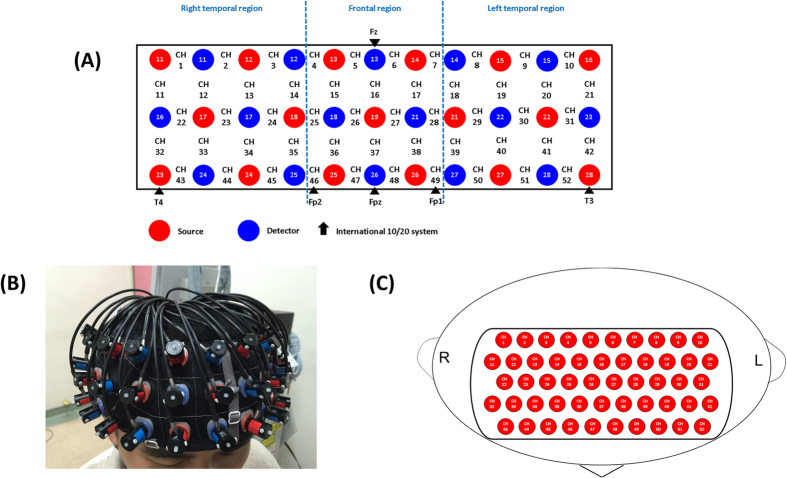
Figure 4. Probe setting and measurement points for 52-channel NIRS.
(A) The localizations of all 52 channels were positioned according to the international 10–20 system. Red and blue circles indicate near-infrared light emitter and detector positions, respectively. By using the international 10–20 system, the detector 13 was positioned on the F z marker point, while the bottom row of channels was placed on a line between T 3 and T 4. (B) Probes with thermoplastic 3 × 11 shells were placed over bilateral frontotemporal regions. (C) The 52 measuring areas are labelled as ch1 to ch52 from the right posterior to left anterior.

