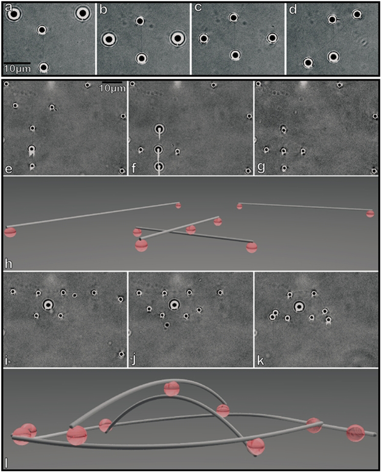
Figure 3. 3D network assemblies.
Demonstration of dynamic control of a MT intersection (a–d). 2 dumbbells are situated perpendicular to one another with the horizontal dumbbell raised relative to the vertical dumbbell by approximately 5 μm (a). The dumbbells are overlaid (b), then positioned at the same height (c), then reoriented to make a 45° angle (d), demonstrating the ability to adjust MT network geometry on demand. Assembly of a static 3D network (e–l). Four dumbbells are assembled, with one dumbbell featuring a BH attached in the middle (e). Two dumbbells are overlaid (f) and then bound together via the BH at the point of intersection (g). The 3D schematic of the resulting arrangement is shown in (h). The MT cross is reoriented and the outlying BHs are brought closer to the center until the central BH is displaced by ~3.5 μm out of the base plane (i). The apparent diameter of the central bead is larger due to the bead being displaced from plane of focus. Additional dumbbells are then “wound” around the cross’s peripheral BHs (i,j). The 3D assembly is then let go by the HOTs (k) and is able to maintain its own structure. 3D schematic for the final assembly is shown in (l).

