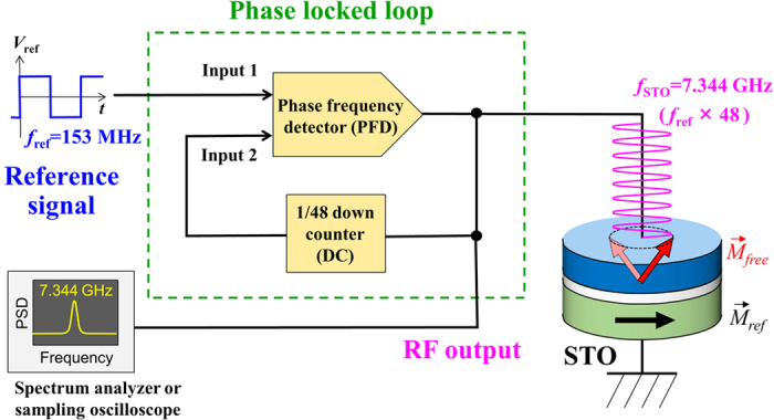
Figure 1. Simplified block diagram of the phase locked loop built in this work.

The functionality of each block is as follows. Spin torque oscillator (STO) is nominally biased to oscillate at around 7.344 GHz. Down counter (DC) down counts the input signal by 48, thus converting 7.344 GHz RF signal to 153 MHz. Phase frequency detector (PFD) generates a voltage signal proportional to the phase error between the two input signals, which is fed back to the STO to dynamically stabilize the oscillation such that the phase error is always minimized.
