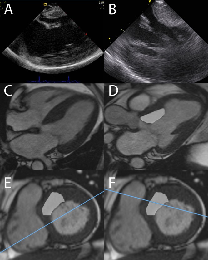
Figure 6.

(A) shows a typical ICE image taken from phase 1. It is similar projection to a TTE four-chamber view taken from inside the RV. (C) shows a typical four chamber view In CMR. (E) shows a short-axis cut of the same heart. The blue line represents the cut of the LV that is shown in (C). The shaded area is the target for ASA. The blue line clearly passes through the inferior septum, missing the target area. (B) shows an ICE image with the true LVOT in view. This is represented in the three-chamber cardiac magnetic resonance (CMR) image in (D). The shaded area is the target for ASA. (F) shows the corresponding short-axis view, the blue line this time passes through the target myocardium in the true septum.

 This work is licensed under a