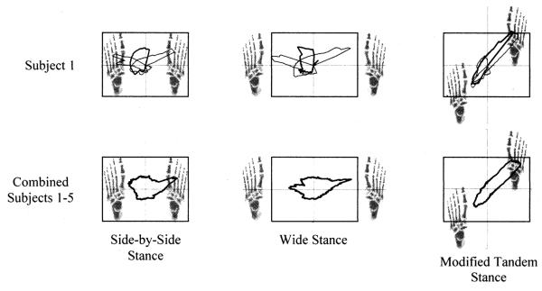
Fig. 5.
COP trace boundaries as a function of foot placement. The first row of traces was taken from individual trials that were representative of the group, while the second row of traces are averages over five subjects and three repetitions. In the first row, the right and left reach COP trace boundaries are represented with thin lines and the center reach COP with a thick line. In the second row, a thick line represents a composite of all three reach directions.

