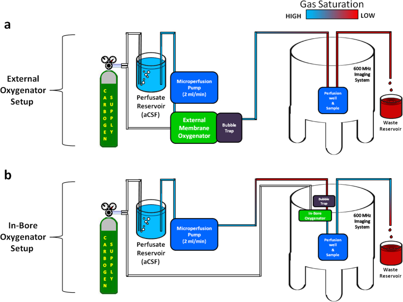
Figure 3. Block diagrams of the microperfusion rig in dual oxygenator configurations.
(a) External oxygenator setup. Excessively long microperfusion lines (5 m) (Cole-Parmer, 06508-13) between the external oxygenator (45 cm wide × 60 cm tall × 30 cm deep) and perfusion chamber lead to significant degassing of our aCSF perfusate prior to encountering the tissue slice. This degassing was responsible for the low oxygen (O2 loss) and high pH (CO2 loss) conditions recorded in the perfusion chamber with the external oxygenator setup and was encountered despite our use of perfusion lines designed for high gas retention. (b) In-bore oxygenator setup. The membrane oxygenator (19 cm tall × 1 cm dia.) and bubble trap (9 cm tall × 1 cm dia.) portions of the microperfusion rig have been redesigned using MR-compatible materials exclusively. In addition, the dimensions of these components have been reduced such that they are now able to fit directly inside the narrow channel of the spectrometer bore (3.5 cm dia.). While significant degassing still occurs between the carbogen bubbled aCSF reservoir and imaging spectrometer, the in-bore oxygenator device drastically reduces the length of perfusion line between the terminal point of gas exchange and the tissue sample (2.5 cm) thus preserving physiologically relevant dissolved oxygen and pH values.

