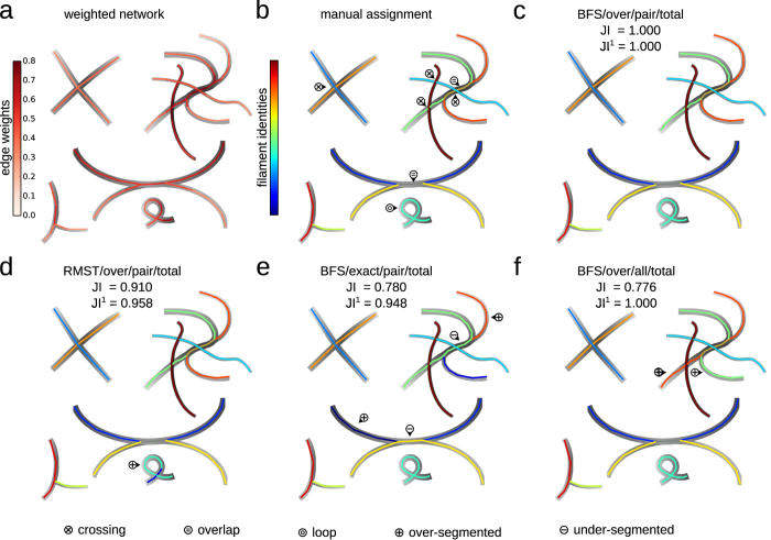
Figure 1. Filament covers of artificial network with crossings, overlaps, and a loop.
(a) Weighted, artificial network extracted from the underlying drawing, with colour-coded edge weights representing the local image intensity. (b) Manual decomposition of the network into filaments with colour-coded indices. The filaments display crossings (⊗), overlaps ( ), and a loop (
 ). (c) Filament cover obtained by solving the FCP using the set of input paths generated by a modified breadth-first-search (BFS), allowing overlapping filaments (over), employing the pairwise roughness measure (pair), and by minimising the total roughness of the cover (total). The automatically obtained filament cover correctly captures crossings, overlaps, and loops, and agrees excellently with the manual assignment (similarity of the two filament covers is measured by the global Jaccard index, JI, and our modified, structure-aware Jaccard index, JI1, which reflect the fraction of pairs of all or only adjacent edges that are assigned to the same filament, respectively; here JI = JI1 = 1). The filament identities and colours are matched by solving an assignment problem whereby the total number of edges shared by two filaments, from the manual and automated partitioning, is maximised; the same assignment procedure is used for the remaining panels. (d) When using paths obtained from sampling random minimum spanning trees (RMST) for the FCP, the closed filament loop is not correctly detected and is over-segmented (
 ). (e) When solving the exact FCP (exact), the loop is correctly detected. However, overlaps are neglected so that no two filaments share an edge, leading to over- and under-segmentation (
 ). (f) When minimising the all-to-all filament roughness (all), two half-filaments are interchanged because the maximum weight difference is smaller along the altered filaments.

