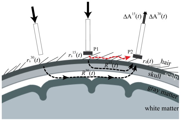
Fig. 3.
Schematic illustration of the proposed method with combined use of the multidistance optode arrangement and the short-circuited light elimination method. For eliminating short-circuited light from the source to detector optodes at S-D pairs of 15 mm distance, polarizers P1 and P2 were arranged in orthogonal directions with each other. and , transmittances of optode–scalp gaps at source optodes of 30 mm and 15 mm distance from the detector optode, respectively; and , transmittances of head tissues when S-D pairs of 30 mm and 15 mm were used, respectively; , transmittance between the detector optode and scalp surface; and , absorbance changes when S-D pairs of 30 mm and 15 mm were used, respectively.

