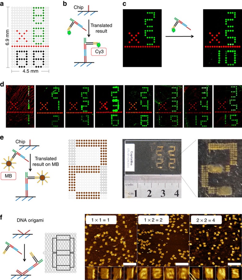
Figure 5. Displaying the results of multiplication reactions on seven-segmented displays.
(a) The design of the first DNA chip used to display the results. The values of inputs X and Y are printed with Cy3, an operator of ‘ × ' and a line are printed with Cy5-labelled strands. Host strands are printed on the output area for digital display of calculated results. (b) The recognition between host and translated result. (c) Fluorescent images by a plate reader of the chip before and after the result–translator complex was added. (d) The results of a series of multiplications imaged by a plate reader. (e) Displaying the result by immobilization of the result–translator complex connected to MBs on a DNA chip. The right-hand panel shows a photo and its magnification of the result of the 1 × 2 multiplication. (f) Immobilization of the unlabelled result–translator complex on V-shaped patterns on DNA origami and imaging of the output numbers of three multiplications using AFM. Scale bars, 500 nm.

