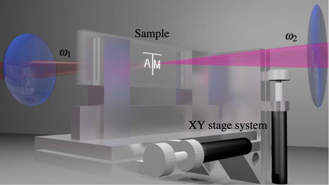
Figure 2. Schematic of the imaging setup.

For illustration, the pump and probe beams are red  and magenta
  , respectively. Two glass slides are sandwiched together with 1 mm of separation between them and sealed to form a cell that was filled with water. The entire sample was mounted on a motorized xy stage system. See Methods section for further details.
