Fig. 3.
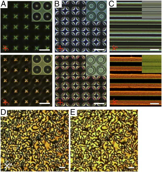
POM and BF images of 5CB and LCM_X1. (A–C) POM and BF images of 5CB (Top panels) and LCM_X1 (Bottom panels) in (A) porous membranes (diameter, 10 µm; pitch, 15 µm; depth, 20 µm), (B) pillar arrays (diameter, 10 µm; pitch, 20 µm; height, 19 µm), and (C) square channels (width, 10 µm; pitch, 40 µm; depth, 20 µm) with homeotropic anchoring imposed at all surfaces. (A, Insets) BF image of LCs in pores where the dark dots at the center show possible defects; (B, Insets) BF image with black circles showing possible bulk line defects circumscribing the pillars; (C, Insets) BF image of a single ridge where the gray color indicates a distorted director field but no defect; (D and E) POM images of the schlieren texture of LCM_X1 before (D) and after (E) UV curing. The nearly identical nematic schlieren textures indicate that the LC director field is well maintained during polymerization. The slight change in color can be attributed to the difference in UV-vis absorption of monomer vs. polymer (SI Appendix, Fig. S5). After polymerization, the LCM-X1 appeared somewhat yellowish. (Scale bars, 20 µm.)

