
Figure 2. Topology diagrams of the NEC subunits and conservation of the Bergerat fold.
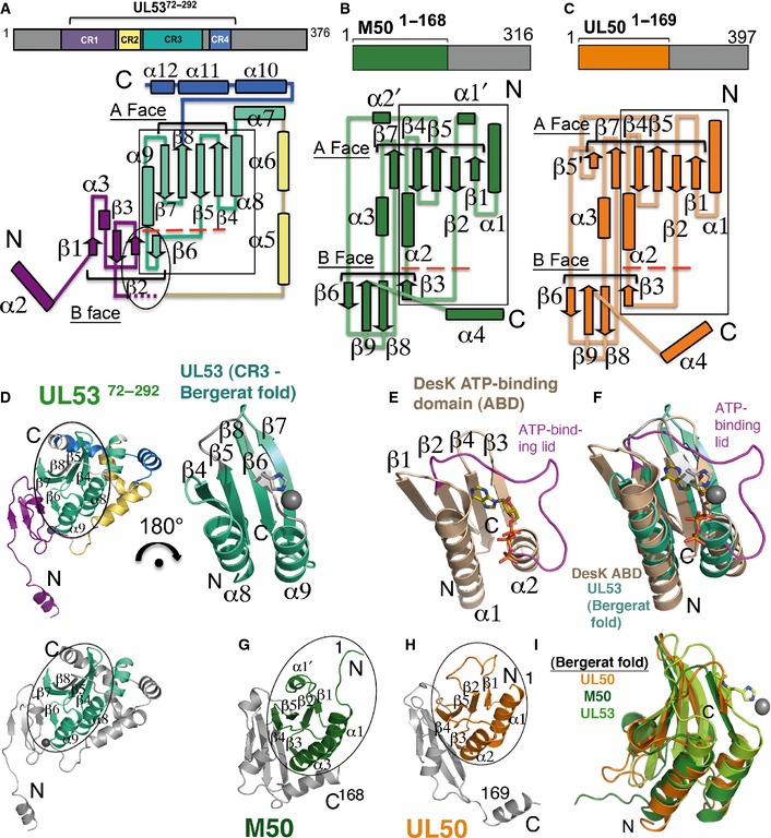
- Topology diagram of the structure of UL5372–292 with the CRs mapped and color‐coded according to the schematic above the structure. The structure begins at α2 (in purple) at the N‐terminus (N) and ends at α12 (in blue) at the C‐terminus (C). Secondary structure elements are numbered, with tubes representing helices and arrows representing strands. The A and B faces of strands are indicated. The region forming the zinc finger is indicated in the oval. The flexible region (observed across the different UL53 structures) encompassing α4 after β3 is indicated with small purple dashes. Conservation of the Bergerat fold is shown with a box. Below the large red dashes, UL53 has its β6 strand in place of an ATP‐binding loop/lid region found in other proteins with the Bergerat fold.
- Topology diagram of the structure of M50. The boundaries of the structure fully encompass the conserved core of the protein and are shown in green in the schematic above the topology diagram. Secondary structure elements are shown with tubes representing helices and arrows representing strands. To facilitate the comparison with UL50 (presented in C), the nomenclature used here for M50 [which differs from that described previously (Leigh et al, 2015)] is the same as that for UL50, with secondary structure insertions designated with a prime (‘). The A and B faces of β‐strands are indicated. Similar to (A), M50 has a β‐strand (β3) shown below the large red dashes in place of an ATP‐binding loop/lid region found in other proteins with the Bergerat fold.
- Topology diagram of the structure of UL501–169. The boundaries of the structure fully encompass the conserved core and are shown in orange in the schematic above the topology diagram. Secondary structure elements are shown with tubes representing helices and arrows representing strands and are numbered similarly to that in M50 (presented in B) with insertions designated with a prime (‘). The A and B faces of strands are indicated. The β3 strand shown below the large red dashes substituting for an ATP‐binding loop/lid region and completing the B face of the β‐taco fold observed in M50 (B) is also conserved in UL50.
- (Left) UL5372–292 with the Bergerat fold circled. The color scheme follows that in (A). (Right) 180° rotation of just the Bergerat fold (encompassing most of CR3). In place of an ATP‐binding loop/lid region is the β6 strand (shown in gray), with a histidine which coordinates zinc (gray sphere). (Bottom) UL5372–292 in the same orientation as the structure shown above and to the left but with the rest of the structure, except for the Bergerat fold shown in gray.
- The Bergerat fold in the DesK ATP‐binding domain (ABD) (Trajtenberg et al, 2010; PDB ID: 3EHG). The ATP‐binding loop/lid region is shown in magenta around the ATP molecule.
- Superposition of the Bergerat fold in UL5372–292 (green‐cyan, from D) onto that of DesK (brown, from E).
- M50 (in the same orientation as UL5372–292 in D) with the Bergerat fold circled (green) (Leigh et al, 2015; PDB ID: 5A3G).
- UL50 (in the same orientation as UL5372–292 in D) with the Bergerat fold circled (orange).
- Overlay of UL5372–292 (limon) onto M50 (green) and UL50 (orange). The histidine on the β6 strand is shown coordinating with zinc (gray sphere).