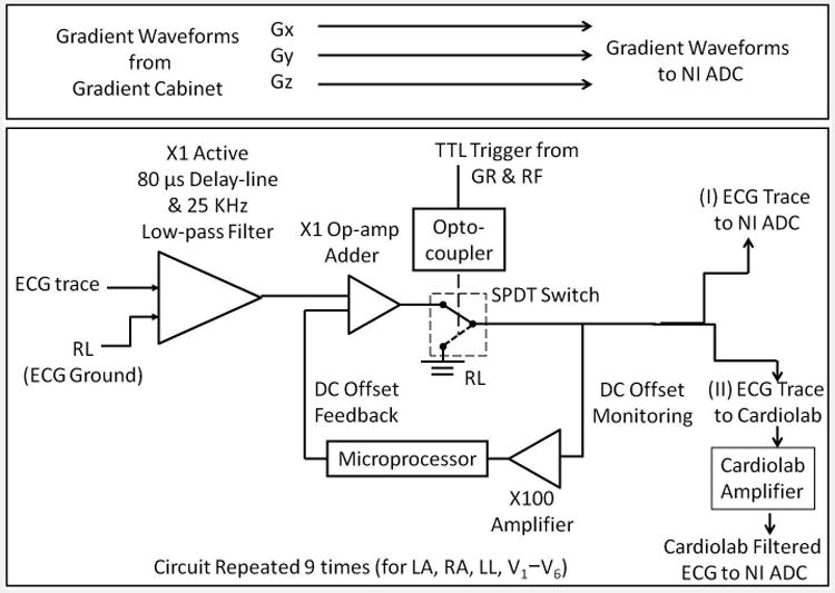
Figure 2.

Block diagram of the MRI-conditional 12-lead ECG front end. The front end enabled patient-isolation via a differential pre-amp/delay-line at its input. It also allowed for blocking strong signals via a TTL-controlled single pole, double throw (SPDT) switch. The circuit had two outputs. Set-up I sampled ECG waveforms in their spectral form without any filtering, while Set-up II sampled using the CardioLab IT digital electrophysiology recording system.
