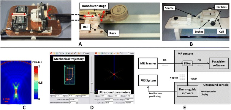
Fig. 1.

Overview of the setup. a On the left, the block with the motors stays outside the magnet, and the movement is transmitted to the transducer on the right via a glass fiber stick. The cradle is holed to welcome an interchangeable bed which is plugged into it. b An interchangeable bed including a plastic head holder with ear bars and bite bar and a dedicated ultrasound transparent coil. c Simulation of the acoustic pressure field generated by the 1.5-MHz monoelement transducer A. d A screen print of the software used to drive the motors and the ultrasound. e A scheme of the real-time data transmission and reconstruction
