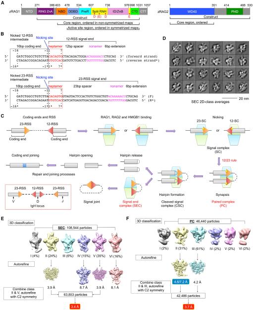
Figure 1. Cryo-EM Structure Determination.
(A) Domain organization of zebrafish RAG1 and RAG2 (zRAG1 and zRAG2). NTD, N-terminal domain; RING ZnA, RING domain and zinc finger A domain; NBD, nonamer binding domain; DDBD, dimerization and DNA binding domain; PreR, pre-RNase domain; RNH, RNase H-like domain; ID/ZnB, insertion domain/zinc binding domain B; CTD, C-terminal domain; CTT, C-terminal tail; WD40, WD40 repeat domain; and PHD, plant homeodomain. Approximate domain boundaries are shown by residue numbers. Potential active site residues are indicated as red dots in RNH.
(B) Recombination signal sequences used in this study. Heptamer sequences (red) are numbered from 1 to 7 for the forward strand and from 1* to 7* for the reverse strand. Coding segment ends are numbered from −16 to −1 for the forward strand and from −16* to −1* for the reverse strand. The nicking site is between A-1 (coding end) and C1 (signal end) with a 3′-OH on the A-1.
(C) Overview of V(D)J recombination. In the red box, RSSs flanking V, D, and J segments in the IgH locus are illustrated. The dimeric (RAG1-RAG2)2 complex is shown as stacked cyan and lemon green trapezoids. Briefly, RAG binds a single RSS in the presence of HMGB1 to form a signal complex (SC), either 12-SC or 23-SC, which can undergo nicking at the coding end-signal end junction in the presence of Mg2+. Synapsis of one 12-RSS and one 23-RSS in the same RAG dimer forms the paired complex (PC), followed by generation of the cleaved signal complex with hairpin coding end and cleaved signal end. Hairpin release produces the signal end complex (SEC). Further processing by enzymes in the non-homologous end-joining DNA repair pathway results in ligation of the coding ends and circularization of the signal ends.
(D) Representative 2D class averages of cryo-EM particles of the SEC.
(E and F) Flow charts of cryo-EM structure determination for the SEC (E) and the PC (F). The two numbers in the blue box are the resolutions of the entire molecule and the NBD region only, respectively.
See also Figure S1.

