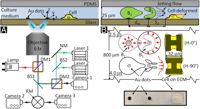
Fig. 1.
Schematic diagrams of tandem bubble generation, jet formation, and resultant flow interaction with a single cell grown nearby in a microfluidic channels. (A) Experimental setup. Two Nd:YAG lasers (laser 1 and laser 2) are projected through a 63X objective (path shown in green) and focused onto a pair of gold dots (6 µm in diameter and 15 nm in thickness) coated on the glass substrate of the microchannel, separated by an interbubble distance (dIB) of 40 µm. Two high-speed video cameras: a Shimadzu HPV-X (camera 1) and a Phantom v7.3 (camera 2) are used to record bubble–bubble–cell interaction when the fluorophore cube with a dichroic mirror (DM1) is off the light path and the beam splitter (BS1) is at 80/20 position. Thereafter, the fluorophore cube is switched back with BS1 at 0/100 position for fluorescent imaging (path shown in red) using a Zeiss AxioCam MRc 5 (camera 3) and a Xenon light source (Lamp). Imaging acquisition with camera 2 or 3 (path shown in black) is controlled by a rotating mirror (RM) underneath BS1. (B) Illustration of the dynamic interaction of tandem bubbles and the resultant deformation of a target cell (shown in dashed line). Bubble–bubble–cell interaction is conducted in the microchannel with dimension of 800 × 25 µm. Single HeLa cells are confined and grown within a 32 × 32 µm island coated with fibronectin. Two fibronectin coated patterns are used, namely H-0° and H-90°, corresponding, respectively, to the case where the proximal edge of the adherent cell is firmly attached onto the substrate or free standing. The standoff distance (Sd) between the leading edge of the cell and the center of the closer gold dot is varied from 10 to 40 µm in different units of the gold-dots/fibronectin island distributed inside the microfluidic channel for high-throughput experiments.

