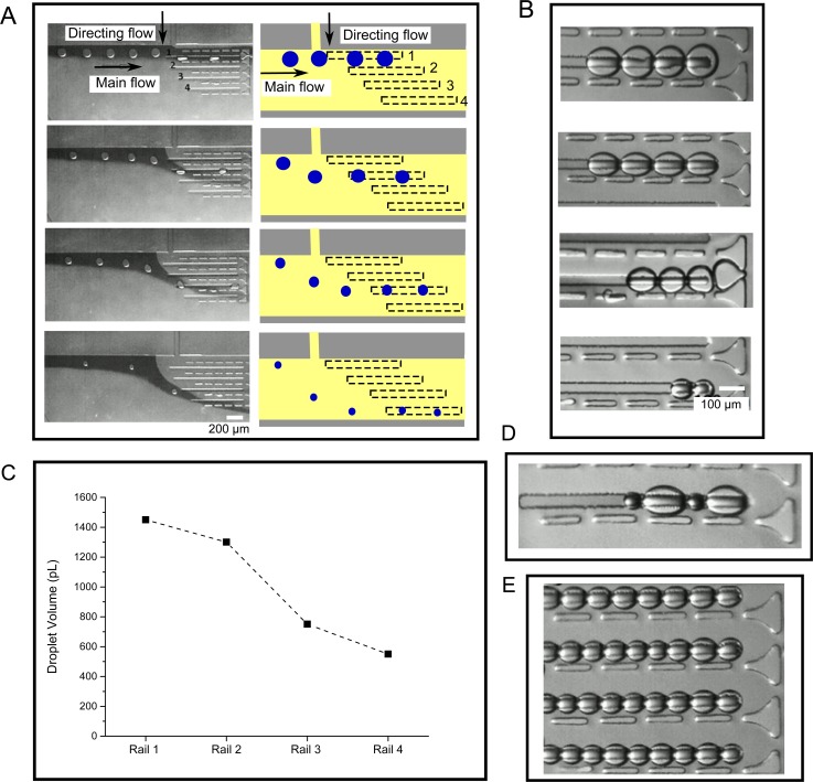
FIG. 3.
(a) Droplets of varying sizes were guided into each of the four rails via a directing flow, with the larger droplets directed to Rail 1 at the top of the image, and smaller droplets to Rails 2, 3, and 4 at the bottom. Dye was added to the main flow to provide a contrast allowing the flow direction to be visualised. (b) Images of different sized DIB networks in the four rails. (c) Graph showing the average volume of droplets present in the four rails (N = 10). (d) Example of a DIB networks with variable droplet sizes on a single rail. (e) Image of a multi-array DIB network, with uniform droplet sizes.

