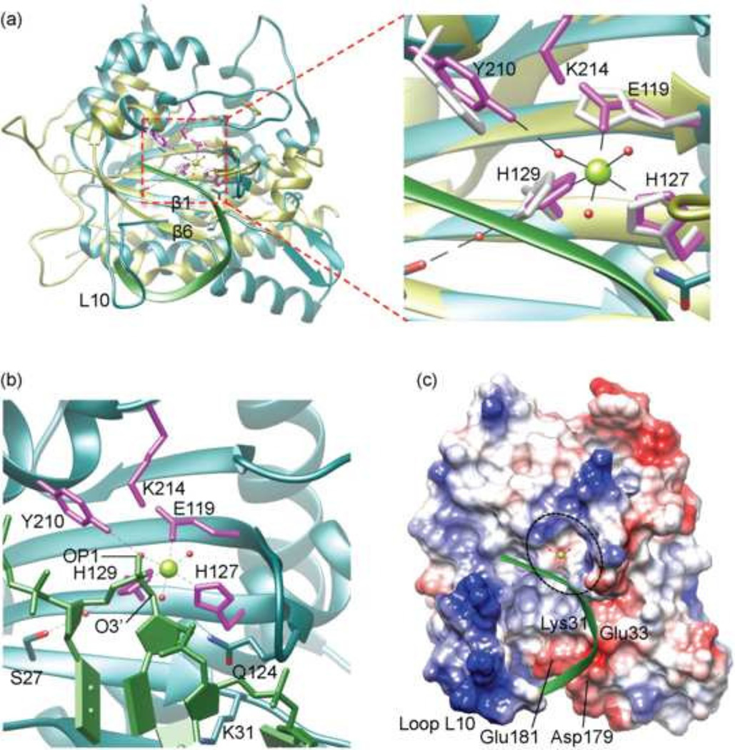
Fig 3. A model for binding of MVM NS 1N to the ssDNA substrate.
(a) Superposition of MVM NS1N (cyan) with TraI (yellow; RCSB PDB entry code 2a0i). The nickase active site residues are shown as stick models in magenta for MVM NS1N and yellow for TraI. The bound Mg2+ in MVM NS1N is shown as a green sphere. The backbone of the bound ssDNA in TraI is shown as a ribbon diagram in green. Structural elements loop L10, β1 and β6 are labeled for clarity.
(b) Closeup of the MVM NS1N nickase active site docked with the ssDNA (green) from TraI. The three water molecules coordinated with the Mg2+ are shown as red spheres. Notice the OP1 and O3’ atoms of ssDNA (indicated) nearly overlap with two Mg2+-coordinating water molecules respectively.
(c) Electrostatic potential surface of MVM NS1N with docked ssDNA (green ribbon diagram) showing how the DNA aligns with the nickase active site (dashed ellipsoid) and approaches the catalytically essential metal ion (green sphere). Residues Lys31, Glu33, Asp179 and Glu181 as well as the loop L10 are indicated.

