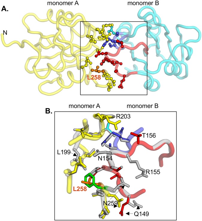
Fig 7. The interfaces formed by the wild type and the F258L mutant.
A. The crystallographic interface formed by the JCV T-ag OBD F258L mutant. Monomer A is shown in yellow, while monomer B is in cyan. In monomer A, residue L258, situated in the C-terminal pocket, is presented in orange. In monomer B, residues from the A1 loop are shown in red; those from the B2 loop are in blue. Side-chains of residues involved in the interface are presented as ball and stick. B. Close-up of the superposition of the interfaces formed by the F258L mutant (colored as described above) and the wild type OBD interface, shown in gray. Residues that are labeled participate in interface formation and differ between the wt and F258L mutant. L258 is shown in orange, F258 in green.

