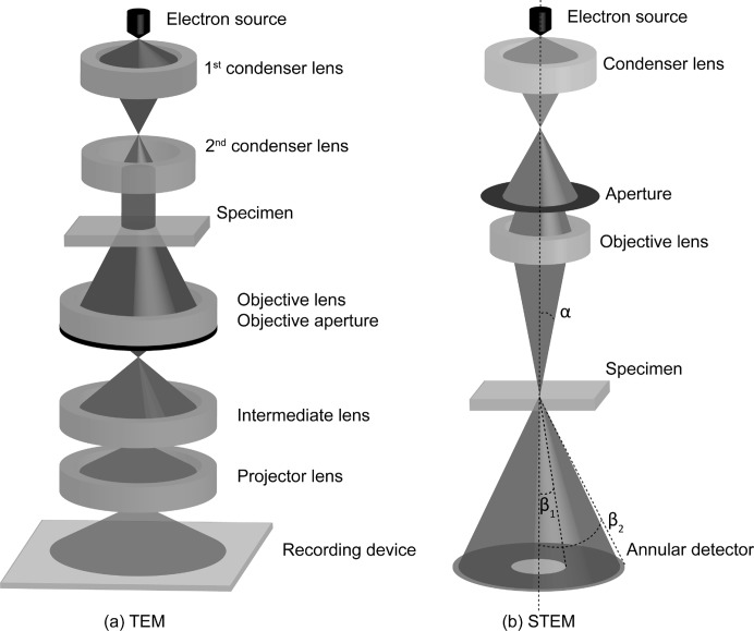
Figure 1.
General schematics of (a) a TEM and (b) a STEM instrument. (a) A plane wave illuminates the object, after which an image is formed using a set of electromagnetic lenses. (b) An electron beam with convergence angle α is scattered by the specimen and collected by an annular detector with inner and outer angles β1 and β2, respectively.

