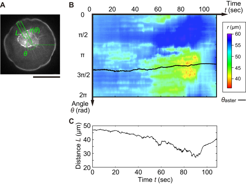
Figure 3.
(A) Geometrical configuration of the position of the interface and the aster core from the projected droplet center of mass in polar coordinate. Scale bar is 50 μm. (B) Color map of the spatiotemporal radial position of the interface  . Black line represents the angular position of the aster core
  . (C) Corresponding distance L between the radial position of interface
  and the center of core as a function of t.

