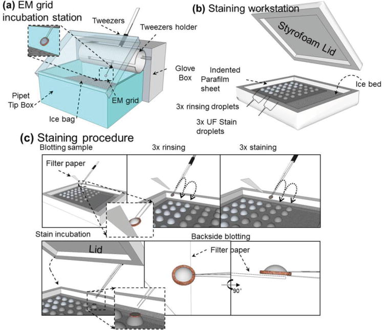
Figure 10.

A schematic diagram of optimized negative-staining (OpNS) procedures. a) Incubation station designed to hold a glow-discharged TEM grid pre-coated with a thin carbon film, which incubates a 3 μL sample solution above an ice bath. b) Staining workstation designed to hold water droplets and stain droplets above an ice bed while minimizing stain exposure to light. c) Overview of the staining procedure. The TEM grid with sample was prepared via 3× water washing, 3× UF stain exposure and followed by backside blotting with a filter. The grid was then dried immediately by nitrogen gas. Reproduced with permission.[181] Copyright 2014, The Authors, published by Journal of Vizualized Experiments (JoVE).
