Fig. 1.
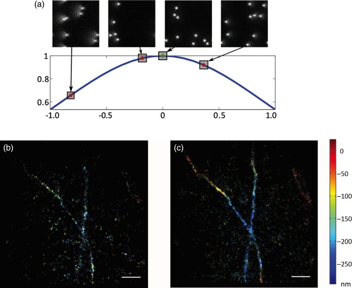
Aberration correction in a SMS microscope. (a) Principle of image-based optimization. For each mode used in the aberration correction procedure, different amplitudes are applied and their correspondent metric value is computed. Fitting of the resulting curve provides the coefficient that maximizes the metric and thus corrects the aberration mode. (b) 3D STORM image of Alexa 647-labelled microtubules obtained using the astigmatism method without aberration correction. (c) 3D STORM image of the same structure when aberrations were corrected; a significant increase in accepted fits is observed. In b and c, the images were taken 6 µm deep into the cell, and the z position is represented by the colour scale. (Images reproduced with permission from Ref. [14].) In b and c, scale bars are 1 µm.

