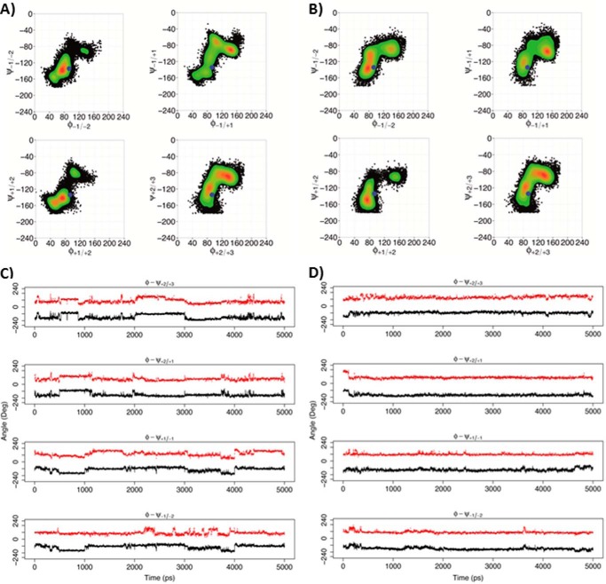
FIGURE 11.
Rotations around the glycosidic linkages for the X5XM4 substrate. A and C, non-processive Ani-PME2. B and D, processive Ech-PME. A and B, φ/ψ dihedral angles for glycosidic linkages +2/+3, +2/+1, +1/−1, and −1/−2, where +1 is the residue X at the active site (+1). The φ and ψ angles are defined, respectively, as O5-C1-O1-C4′ and C1-O1-C4′-C3′ (see Fig. 1). The blue dots mark the starting point for the MD simulations. The scale on the right reports the relative probability of the φ/ψ values sampled during the MD simulations. C, plot of φ (red) and ψ (black) dihedral angles as a function of time for the non-processive Ani-PME2, showing uncorrelated and non-concerted rotations. D, plot of φ (red) and ψ (black) dihedral angles as a function of time for the processive Ech-PME, showing correlated and concerted rotations. The plots in B and D were obtained from the MD trajectories as published previously (74).

