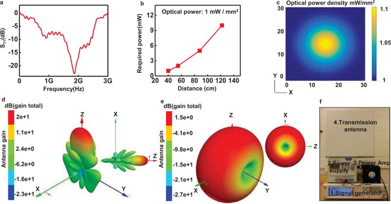
Fig. 2.
Characteristics of the harvester the RF systems. The harvester includes an antenna, an impedance matching circuit and a Villard cascade voltage multiplier (8× multiplication, to enable broad wireless coverage). (a) Scattering parameter, S11, of the receiving antenna. (b) Transmitted power required to operate the μ-ILEDs, as a function of distance. (c) Plot of the computed spatial distribution of optical power density vertically incident across the cage (30 cm by 30 cm). 3D plots of radiation patterns of the transmission (d) and harvester (e) antennas. (f) A picture of the RF systems:1.signal generator, 2.power amplifier, 3.power supply, and 4.transmission antenna.

