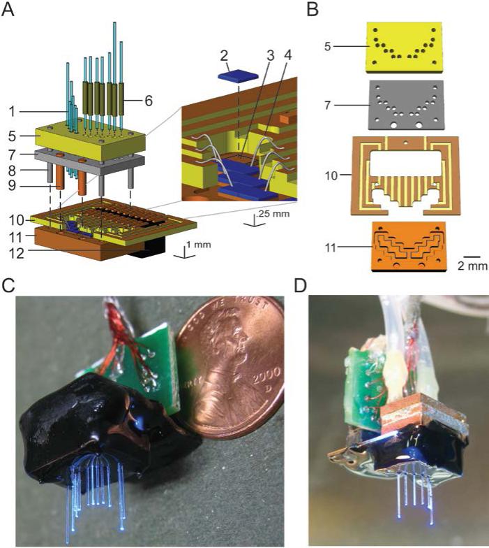
Figure 1. Design and fabrication of optical fiber arrays.
A, Schematic, in exploded view, of a fiber array with fibers pointing upwards, with inset zoomed in on LEDs and their connections, adapted from refs. [8-10]. Vertical dashed lines denote points at which components dock together when the device is assembled. Numbers refer to key components: 1, optical fiber; 2, LED; 3, LED pedestal (carved out of LED base plate, 11); 4, wire bond; 5, fiber alignment plate; 6, fiber fitting; 7, reflector plate; 8, device assembly guidepost (to be removed after final assembly, but before implantation); 9, reflector plate heat conduit; 10, circuit board; 11, LED base plate; 12, circuit board connector. B, Key structural components, numbered the same as in A. C, Photograph of a relatively dense hippocampal CA1-targeted fiber array device (schematized in A), appropriate for silencing the entire hippocampus for example, with fibers pointing downwards, with a penny for scale. D, An 8-fiber hippocampal array, appropriate for stimulating multiple points in the hippocampus, shown with optional cooling module before encapsulation with biocompatible epoxy.

