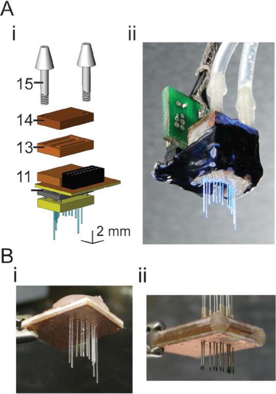
Figure 2. Accessory devices, and modifications, for implantation and utilization of fiber arrays.
A, Fluidic cooling system, added to the back of the fiber array, appropriate for increasing the amount of time the array can be run continunously. i, Schematic, in exploded view, of the cooling system, added to the back of the fiber array. Numbers refer to key components: 11, LED base plate; 13, fluidic cooling channel plate; 14, fluidic cooling channel backing plate; 15, barbed fluidic connector. ii, Photograph of a cooled hippocampal CA1-targeted fiber array (based on the design in Figure 3Ai). B, Accessory devices to aid fiber array implantation. i, Practice array, with the same targets as the array schematized in Figure 2A, shown during fabrication before encapsulation with biocompatible epoxy. ii, Parallelized craniotomy marker, consisting of freely-moving hypodermic steel tubing with inked tips, appropriate for conforming to the contours of the skull and marking sites of craniotomies for fibers.

