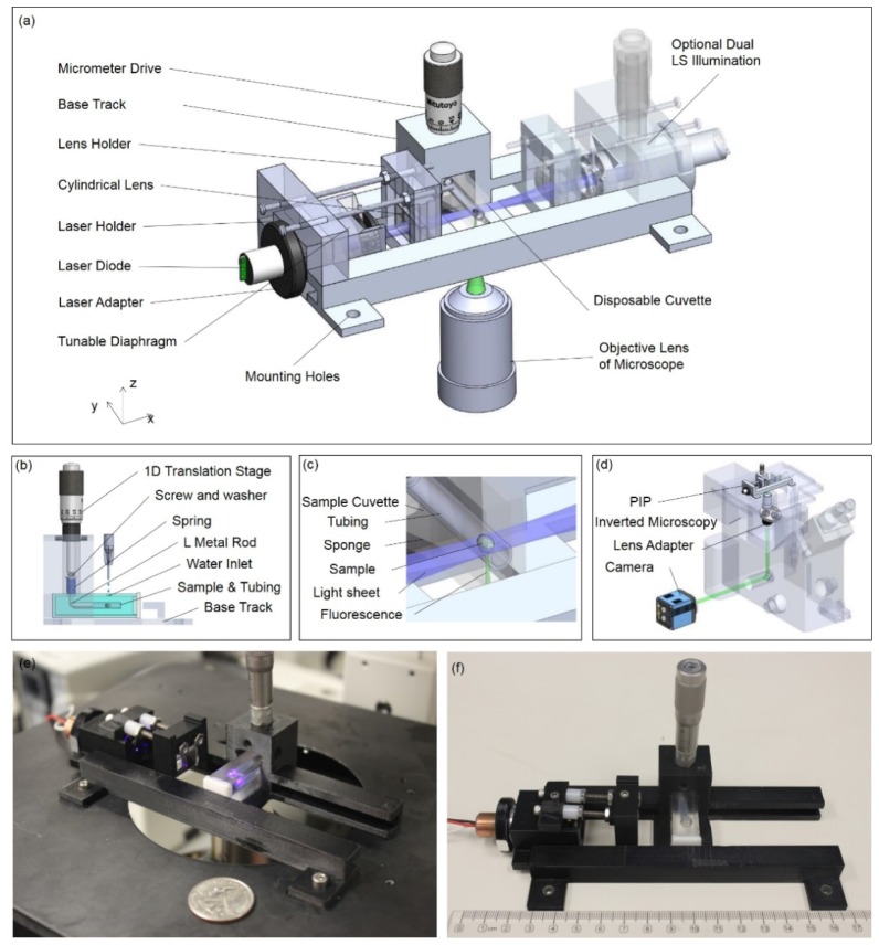
Fig. 1.
Schematic of the Plane Illumination Plugin (PIP) and its working principle. (a) The configuration of the PIP, which is based on fast 3D printing and several small optics. The key components include a laser diode module as light source, a cylindrical lens for light sheet generation, a micrometer drive for optical control, and a disposable cuvette as the sample holder. (b) Sample manipulation setup in PIP. A FEP tubing with sample mounted inside is connected to a micrometer via an L shape adapter. By tuning the micrometer, the sample together with the tubing can be vertically scanned through the light sheet, inside a water environment. (c) The working status of the PIP. The laser sheet propagates horizontally through the sample, generating a plane illumination on the fluorophores. The existing fluorescence detection system inside the microscope collects the sample signal and images it onto the camera. (d) The working principle of PIP with a Nikon Eclipse TE-2000 inverted microscope. A lens adapter is added on the objective lens to increase the working distance. Through mounting the PIP on the stage and inserting the sample, LSFM is enabled on a conventional wide-field microscope. (e), (f) show the photographs of the real PIP device with (e) the scene of PIP device working with a Nikon TE-2000 inverted microscope. (f) The image of PIP with ruler showing its dimensions.

