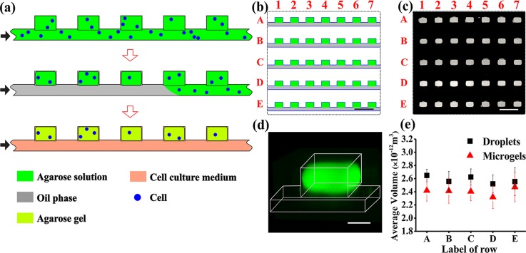
FIG. 1.
Microfluidic generation of hydrogel modules (HMs). (a) Schematic of the MF generation of the 2D array of cell-laden agarose HMs from top view of the channel and wells. Step 1: cell suspension in an agarose solution is perfused through the microfluidic device. Step 2: the agarose solution in the supplying channel is switched to an oil phase. Droplets of agarose solution are confined in the wells, and cells are entrapped into the droplets. Step 3: the temperature is lowered to 4 °C to transform the droplets of agarose solution into gels (HMs). After HM formation, the oil phase in the supplying channel is replaced with a cell culture medium. The black arrows show the direction of infusion of liquid phases: top to bottom: agarose solution or cell suspension in the agarose solution, oil, and nutrition medium. (b) Schematic of the top view fragment of the 2D array containing five rows with seven microwells, each (the entire row contained 100 wells). (c) Fluorescence microscopy image of the top view fragment of the 2D array (shown in (b)), with wells filled with a 2 wt. % solution of agarose conjugated with fluorescein isothiocyanate (FITC). (d) Three-dimensional CFM image of an individual HM formed in the well from FITC-conjugated agarose. The image was obtained by 3D reconstruction of the images with a step of 10 μm. (e) Variation in the average volume of droplets of agarose solution at Cagar = 2 wt. % (▪) and resulting microgels (▲), shown for rows A–E. The dimensions of 90 droplets or microgels in each row were analyzed for the calculations of the average volume. The scale bar is 500 μm in (b) and (c) and 100 μm in (d). Error bars in (e) show standard deviation (SD).

