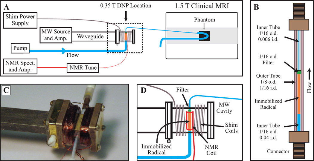
Figure 2.
Panel (A) gives a schematic overview of the entire system for delivering hyperpolarized water to a clinical MRI magnet for imaging. The heating coil, cooling air connection and waveguide-coax adapter between the MW amp and waveguide are omitted for clarity. The dashed outline denotes the section which is expanded in panel (D). Panel (B) presents a detailed drawing of the polarization cell that is placed inside the microwave cavity. All dimensions are in inches, and i.d. and o.d. stand for inner and outer diameter, respectively. The outer tube is Teflon FEP while the inner tubing is Teflon PTFE, and a 2 µm filter (C-407, 0.062 in. o.d., Upchurch Scientific) holds the immobilized radical beads in the cavity. A layer of cyanoacrylate glue is placed between the 0.006 in. i.d. tube and the outer tube, to prevent water from flowing in the space between the two tubes. Panel (C) is a photograph of the microwave cavity showing all connections. Panel (D) gives an expanded schematic of the microwave cavity and connections. Images are available in color online.

