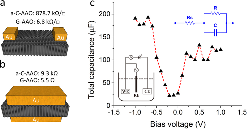
Figure 4. Electrical and electrochemical measurements.
(a,b) Schematic illustrations for resistance measurement horizontally along and vertically across the sample, respectively, where the black porous membranes are the samples (a-C-AAO or G-AAO) and the golden blocks are the contacts. The values indicate the sheet resistance and resistance in (a,b), respectively. (c) The total capacitance variation of G-AAO with the bias voltage changing in ferrocyanide solution. The inset at the lower left corner depicts the three-electrode electrochemical cell, where WE, RE and CE represent working electrode, reference electrode and counter electrode. The inset at the upper right corner is the equivalent circuit (the Randles circuit) between the working electrode and the counter electrode used for evaluation of capacitance.

