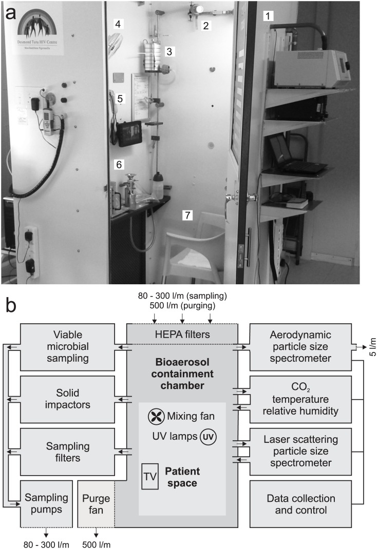
Fig 1. The Respiratory Aerosol Sampling Chamber (RASC).
(A) Photograph of the RASC (with the door open) on site in a community TB clinic (1) aerodynamic particle sizer (2) Filter samplers (3) Andersen impactor (4) Mixing fan (5) CO2, temperature and RH (6) PM10 impactor (7) Chair for participant. (B) Block diagram depicting the fluidic and electronic configuration of the RASC. Thick connecting lines indicate airflow and aerosol paths; thin lines indicate electronic connections. All air leaving the RASC is HEPA filtered.

