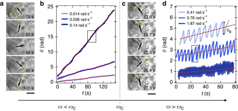
Figure 3. Evidence of wire rotational instability in living cells.
(a) Optical microscopy images of a 2.8 μm internalized wire subjected to a rotating field of 14 mT and the frequency of 0.14 rad s−1. (b) Time dependences of the angle θ(t) at varying frequencies ω=0.014, 0.036 and 0.14 rad s−1. The rectangle around 80 s provides the time range for the images on the left hand side. The straight lines in red were calculated from the expression θ(t)=ωt, indicating that the wire rotates synchronously with the field, and at the same angular frequency. The synchronous rotation of the wire is illustrated in Supplementary Movie 1. (c,d) Same representation as in a,b but for angular frequencies (0.41, 0.76 and 1.87 rad s−1) above the critical frequency ωC=0.15 rad s−1. The microscopy images on the left-hand side shows that after a clockwise rotation, the wire comes back rapidly in an anti-clockwise motion, indicating that the wire rotation is hindered (see Supplementary Movies 2 and 3. Scale bars in a,c are 2 μm.

