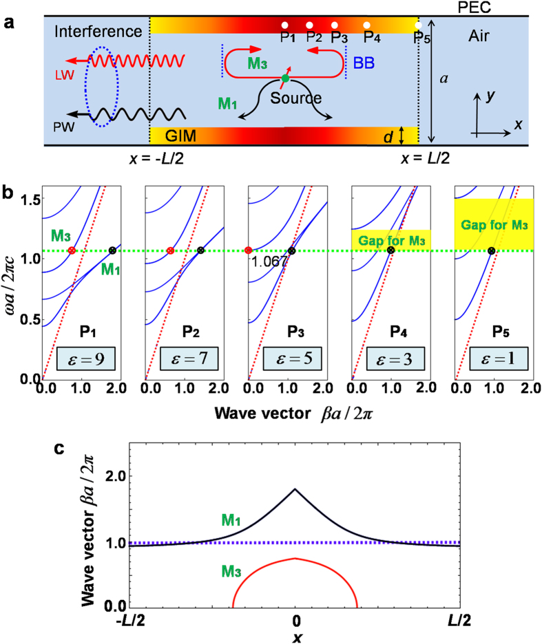
Figure 1. Concept of the designed waveguide structure exhibiting Fano resonances.
(a) Schematic of a paralleled-plated waveguide made from two identical GIMs. The waveguide structure is bounded by walls of perfect electric conductors (PECs). Two black dashed lines illustrate the studied region, in which an excited source, shown by a red arrow with a green point, is located at the centre with coordinate (0,0). Two blue dashed lines show the band bottom (BB) of mode M3 at  1.067. (b) The five discrete dispersion relations for a TE wave, corresponding to five different positions of GIMs (depicted by five white points in Fig. 1a). From left to right, the permittivity is 9, 7, 5, 3 and 1, respectively. The green dashed line shows a working frequency at
  1.067, in which two guided modes M1 and M3 are indicated by black and red point, respectively. The red dashed lines represent light lines. c, The wave vectors of modes M1 and M3 at different positions x in the above structure, at working frequency
  1.067.

